|
Click on any image to see a full-sized version. |
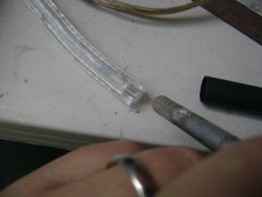 Terminal End Wires Now carefully cut along the top of the wires, right down to their depth, but not into them. This cut is made with the point of the knife drawn along the same direction as the rope light. |
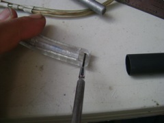 Pulling out the Wires Now use a small screwdriver to pull the wires out. I slide the point of the screwdriver through the slice I just made and under the wires. Then I lever them up and out. |
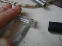 Pulling out the Wires -- continued You will probably have to do this several times for each wire because fine threads of the wire will remain in the channel. Try to get them all without breaking any. |
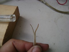
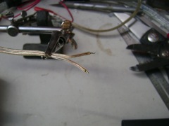
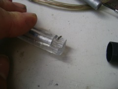 An Exposed Terminal Wire This wire has been pulled out of the plastic sheathing at the terminal end. |
 Tin the Terminal End Once you have pulled out both wires, tin them so they are ready for the next connection. |
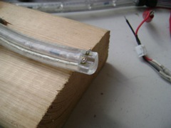
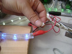 Test the Connections and Mark Polarity Test the entire connected strand of rope lights and mark the polarity. Yes, you've tested at each point, so this is going to work. But you still need to know and mark the polarity on the terminal end. |
 Prepare the Lead Wire I use coolneon connectors to for the ends of my rope lights. They are inexpensive and they are polarized, which means they help you avoid connecting your rope light backwards (once you get the polarity right to begin with, that is). How much lead wire you need depends on how far your power supply is from the end of your rope light. On one end of the lead wire split it about 1/2" and strip about 1/8" of the insulation of each end. |
 Tin the End of the Lead Wire Tin the ends of the lead wires. |
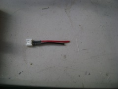 A Coolneon Connector (pin side) I use a pin-side coolneon connector at the terminal end of the rope light. I've cut the ground side (black) shorter than the plus side, so that the two solder joints won't be right next to each other. I like using this end because that means the powered connector end has no exposed pins that can touch metal and create a short circuit. |
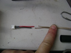 Prepare the Connector End of the Lead Wires The lead wire I use has a white stripe on one of the wires. You probably can't see it in these photos, but I always use the marked strand for plus and the unmarked one for minus. I cut the plus wire short, to match the connector wire lengths, as shown. |
All information herein is Copyright 2009 by Howard Cohen, all rights reserverd Worldwide. |